PyMTL Tutorial: Composing Pure-PyMTL, SystemVerilog, and SystemC
- Author: Christopher Batten, Moyang Wang, Shunning Jiang
- Date: Spring 2017
Table of Contents
- Introduction
- Using PyMTL for Verification of VVADD Accelerator
- Using Stratus HLS for SystemC VVADD Accelerator
- Using PyMTL for Verification of RV32IM Processor
- Using PyMTL for Evaluation of RV32IM Processor
- Using PyMTL for Composition of RV32IM Processor and VVADD Accelerator
Introduction
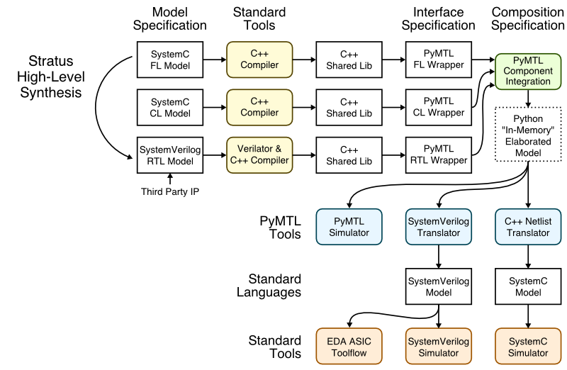
This tutorial demonstrates PyMTL’s ability to serve as a verification and composition framework for SystemVerilog, SystemC, and pure-PyMTL models. The following figure illustrates the overall toolflow used in this framework. SystemVerilog RTL and SystemC FL/CL modules can be imported into the framework using interface specifications which declare the the port mapping along with any additional metadata. Note that we actually compile and wrap SystemVerilog and SystemC modules into simulatable components which can be co-simulated with each other and pure-PyMTL FL, CL, and RTL models using the PyMTL simulator. High-level synthesis (HLS) can be used to automatically transform high-level SystemC FL models into low-level SystemVerilog RTL models. For compositions with pure-PyMTL RTL and SystemVerilog RTL, the final composition can also be translated into SystemVerilog to use with a standard SystemVerilog simulator or to drive either an FPGA or ASIC toolflow. For compositions with SystemC FL and CL, we plan to eventually add support for translating into a SystemC netlist to use with a standard SystemC simulator.
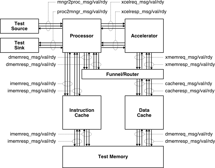
We will use a simple example of composing an in-order, pipelined RISC-V RV32IM processor and a simple vector-vector-add (vvadd) accelerator. The following figure illustrates this system. The processor includes eight latency insensitive val/rdy interfaces. The mngr2proc/proc2mngr interfaces are used for the test harness to send data to the processor and for the processor to send data back to the test harness. The imemreq/imemresp interfaces are used for instruction fetch, and the dmemreq/dmemresp interfaces are used for implementing load/store instructions. The xcelreq/xcelresp interfaces are used for the processor to send messages to the accelerator. The xcelreq/xcelresp follow the Rocket Custom Coprocessor interface (RoCC). For the processor, we have developed pure-PyMTL FL, pure-PyMTL RTL, and SystemVerilog RTL implementations. For the accelerator, we have developed pure-PyMTL FL, pure-PyMTL CL, pure-PyMTL RTL, SystemVerilog RTL, and SystemC FL implementations. We have also used a standard HLS toolflow to automatically transform the SystemC FL model into a SystemVerilog RTL implementation. Each subsystem is verified using py.test, a standard Python-based testing framework, and a mix of directed and random unit testing. This same framework is also used for comprehensive integration testing across the two subsystems. The same tests can be used across all implementations. We can compose and co-simulate the cross-product of our three processor implementations and six accelerator implementations.
This tutorial assumes you have already completed (or at least reviewed) the PyMTL and Verilog tutorials located here:
- http://www.csl.cornell.edu/courses/ece5745/handouts/ece5745-tut3-pymtl.pdf
- http://www.csl.cornell.edu/courses/ece5745/handouts/ece5745-tut4-verilog.pdf
The first step is to clone this repository from GitHub, define an environment variable to keep track of the top directory for the project, make a build directory, and source a setup script.
 % mkdir $HOME/vc/git-hub/cornell-brg
 % cd $HOME/vc/git-hub/cornell-brg
 % git clone git@github.com:cornell-brg/pymtl-tut-composition
 % cd pymtl-tut-composition
 % TOPDIR=$PWD
 % mkdir $TOPDIR/sim/build
 % source $TOPDIR/setup.sh
Using PyMTL for Verification of VVADD Accelerator
We take an incremental approach when designing, implementing, testing, and evaluating systems. We can use test sources, sinks, and memories to create a test harness that will enable us to explore the accelerator cycle-level performance in isolation. Only after we are sure that we have a reasonable design-point should we consider integrating the accelerator with the processor.
All accelerators have an xcelreq/xcelresp interfaces along with a standard memreq/memresp interfaces. The messages sent over the xcelreq/xcelresp interfaces allow the test harness or processor to read and write accelerator registers. These accelerator registers can be real registers that hold configuration information and/or results, or these accelerator registers can just be used to trigger certain actions. The messages sent over the xcelreq interface from the test harness or processor to the accelerator have the following RoCC format:
       7b          5b         5b         1b        1b         1b         5b         7b        64b   64b
 +------------+----------+----------+---------+----------+----------+---------+-------------+-----+-----+
 | inst_funct | inst_rs2 | inst_rs1 | inst_xd | inst_xs1 | inst_xs2 | inst_rd | inst_opcode | rs1 | rs2 |
 +------------+----------+----------+---------+----------+----------+---------+-------------+-----+-----+
Every accelerator is free to design its own accelerator protocol by
defining the meaning of each field, as long as it follows the RoCC
message format. In our accelerator designs, the 7-bit inst_funct field
is used to indicate message type: zero (0) for reading, and one (1) for
writing an accelerator register; the 5-bit inst_rs2 field specifies
which accelerator register to read or write, and the 64-bit rs1 field
is the data to be written.
For every accelerator request, the accelerator must send back a corresponding accelerator response over the xcelresp interface. These response messages have the following format:
     5b         64b
 +---------+-----------+
 | resp_rd | resp_data |
 +---------+-----------+
The 32-bit resp_data field is the data read from the corresponding
accelerator register. The resp_rd field is unused.
The vvadd accelerator protocol defines the accelerator registers as follows:
- xr0 : go/done
- xr1 : base address of the array src0
- xr2 : base address of the array src1
- xr3 : base address of the array dest
- xr4 : size of the array
The actual protocol involves the following steps:
- Write the base address of src0 to xr1
- Write the base address of src1 to xr2
- Write the base address of dest to xr3
- Write the number of elements in the array to xr4
- Tell accelerator to go by writing xr0
- Wait for accelerator to finish by reading xr0, result will be 1
A close look at the vvadd accelerator FL model in
sim/vvadd_xcel/VvaddXcelPFL.py shows that most of the work is really in
managing this accelerator protocol. The accelerator waits for accelerator
requests, updates its internal state registers, and when it receives a
write to xr0 it starts doing the actual vvadd computation. The FL model
makes use of ListMemPortAdapters to simplify interacting with the
memory system.
The unit testing is in the sim/vvadd_xcel/test/VvaddXcelPFL_test.py
test script. This script illustrates how flexible test harnesses can be
created in PyMTL for both directed and random unit testing. More details
of writing and using PyMTL test harnesses can be found in the PyMTL
tutorial. Let’s run the unit tests on the pure-PyMTL FL model first:
 % cd $TOPDIR/sim/build
 % py.test ../vvadd_xcel/test/VvaddXcelPFL_test.py --verbose
We can run one test and enable line tracing to see the FL model in operation.
 % cd $TOPDIR/sim/build
 % py.test ../vvadd_xcel/test/VvaddXcelPFL_test.py -k [mini] -s

     src          xcelreq     xcelresp    memreq           memresp         sink
--------------------------------------------------------------------------------------------
  2:            >           ().         |                ().             > .
  3: wr:01:1000 > wr:01:1000()          |                ().             >
  4: #          > #         ()resp:00:0 |                ().             > resp:00:0
  5: wr:02:2000 > wr:02:2000()          |                ().             >
  6: #          > #         ()resp:00:0 |                ().             > resp:00:0
  7: wr:03:3000 > wr:03:3000()          |                ().             >
  8: #          > #         ()resp:00:0 |                ().             > resp:00:0
  9: wr:04:0004 > wr:04:0004()          |                ().             >
 10: #          > #         ()resp:00:0 |                ().             > resp:00:0
 11: wr:00:0000 > wr:00:0000()          |                ().             >
 12: #          > #         ()resp:00:0 |                ().             > resp:00:0
 13: #          > #         ()          | rd:00:1000:    ()              >
 14: #          > #         ()          |                ()rd:00:0:0001  >
 15: #          > #         ()          | rd:00:2000:    ()              >
 16: #          > #         ()          |                ()rd:00:0:0001  >
 17: #          > #         ()          | wr:00:3000:0002()              >
 18: #          > #         ()          |                ()wr:00:0:      >
 19: #          > #         ()          | rd:00:1004:    ()              >
 20: #          > #         ()          |                ()rd:00:0:0001  >
 21: #          > #         ()          | rd:00:2004:    ()              >
 22: #          > #         ()          |                ()rd:00:0:0002  >
 23: #          > #         ()          | wr:00:3004:0003()              >
 24: #          > #         ()          |                ()wr:00:0:      >
 25: #          > #         ()          | rd:00:1008:    ()              >
 26: #          > #         ()          |                ()rd:00:0:0001  >
 27: #          > #         ()          | rd:00:2008:    ()              >
 28: #          > #         ()          |                ()rd:00:0:0003  >
 29: #          > #         ()          | wr:00:3008:0004()              >
 30: #          > #         ()          |                ()wr:00:0:      >
 31: #          > #         ()          | rd:00:100c:    ()              >
 32: #          > #         ()          |                ()rd:00:0:0001  >
 33: #          > #         ()          | rd:00:200c:    ()              >
 34: #          > #         ()          |                ()rd:00:0:0004  >
 35: #          > #         ()          | wr:00:300c:0005()              >
 36: #          > #         ()          |                ()wr:00:0:      >
 37: rd:00:0000 > rd:00:0000()          |                ().             >
 38: .          > .         ()resp:00:1 |                ().             > resp:00:1
The first few cycles are spent configuring the accelerator, and then the remaining cycle are spent loading from the two source arrays, doing the addition, and storing the result.
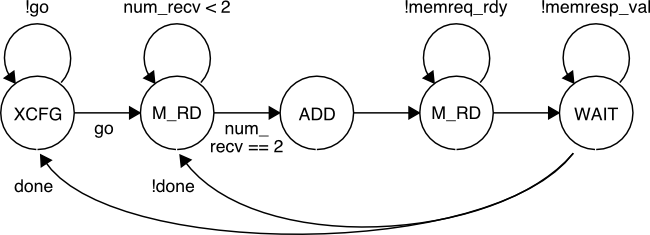
We have also provided pure-PyMTL CL and RTL models for the vvadd accelerator which us a basic FSM to interact with the latency insensitive memory interface and to do the actual addition. The corresponding FSM diagram is shown below.
We can now run the exact same tests on the pure-PyMTL CL and RTL models:
 % cd $TOPDIR/sim/build
 % py.test ../vvadd_xcel/test/VvaddXcelPCL_test.py --verbose
 % py.test ../vvadd_xcel/test/VvaddXcelPRTL_test.py --verbose
We can run one test and enable line tracing to see the RTL model in operation:
 % cd $TOPDIR/sim/build
 % py.test ../vvadd_xcel/test/VvaddXcelPRTL_test.py -k [mini] -s

     src          xcelreq    ST              xcelresp    memreq           memresp         sink
---------------------------------------------------------------------------------------------------
  2:            >           (X  0:0:00000000).         |                ()              > .
  3: wr:01:1000 > wr:01:1000(X  0:0:00000000)          |                ()              >
  4: wr:02:2000 > wr:02:2000(X  0:0:00000000)resp:00:0 |                ()              > resp:00:0
  5: wr:03:3000 > wr:03:3000(X  0:0:00000000)resp:00:0 |                ()              > resp:00:0
  6: wr:04:0004 > wr:04:0004(X  0:0:00000000)resp:00:0 |                ()              > resp:00:0
  7: wr:00:0000 > wr:00:0000(X  0:0:00000000)resp:00:0 |                ()              > resp:00:0
  8: rd:00:0000 > rd:00:0000(X  0:0:00000000)resp:00:0 |                ()              > resp:00:0
  9: .          > .         (RD 0:0:00000000)          | rd:00:1000:    ()              >
 10: .          > .         (RD 0:0:00000000)          | rd:00:2000:    ()rd:00:0:0001  >
 11: .          > .         (RD 1:1:00000000)          |                ()rd:00:0:0001  >
 12: .          > .         (RD 1:2:00000000)          |                ()              >
 13: .          > .         (+  0:2:00000001)          |                ()              >
 14: .          > .         (WR 0:2:00000001)          | wr:00:3000:0002()              >
 15: .          > .         (W  0:0:00000001)          |                ()wr:00:0:      >
 16: .          > .         (W  1:0:00000000)          |                ()              >
 17: .          > .         (RD 0:0:00000000)          | rd:00:1004:    ()              >
 18: .          > .         (RD 0:0:00000000)          | rd:00:2004:    ()rd:00:0:0001  >
 19: .          > .         (RD 1:1:00000000)          |                ()rd:00:0:0002  >
 20: .          > .         (RD 1:2:00000000)          |                ()              >
 21: .          > .         (+  0:2:00000002)          |                ()              >
 22: .          > .         (WR 0:2:00000002)          | wr:00:3004:0003()              >
 23: .          > .         (W  0:0:00000002)          |                ()wr:00:0:      >
 24: .          > .         (W  1:0:00000000)          |                ()              >
 25: .          > .         (RD 0:0:00000000)          | rd:00:1008:    ()              >
 26: .          > .         (RD 0:0:00000000)          | rd:00:2008:    ()rd:00:0:0001  >
 27: .          > .         (RD 1:1:00000000)          |                ()rd:00:0:0003  >
 28: .          > .         (RD 1:2:00000000)          |                ()              >
 29: .          > .         (+  0:2:00000003)          |                ()              >
 30: .          > .         (WR 0:2:00000003)          | wr:00:3008:0004()              >
 31: .          > .         (W  0:0:00000003)          |                ()wr:00:0:      >
 32: .          > .         (W  1:0:00000000)          |                ()              >
 33: .          > .         (RD 0:0:00000000)          | rd:00:100c:    ()              >
 34: .          > .         (RD 0:0:00000000)          | rd:00:200c:    ()rd:00:0:0001  >
 35: .          > .         (RD 1:1:00000000)          |                ()rd:00:0:0004  >
 36: .          > .         (RD 1:2:00000000)          |                ()              >
 37: .          > .         (+  0:2:00000004)          |                ()              >
 38: .          > .         (WR 0:2:00000004)          | wr:00:300c:0005()              >
 39: .          > .         (W  0:0:00000004)          |                ()wr:00:0:      >
 40: .          > .         (W  1:0:00000000)          |                ()              >
 41:            >           (X  0:0:00000000)resp:00:1 |                ()              > resp:00:1
The ST column indicates the state of the vvadd accelerator FSM. We can
see the RTL implementation bringing in elements from the source array,
doing the actual addition, and the writing the result back out to the
destination array in memory.
PyMTL supports translating PyMTL RTL models into SystemVerilog RTL, and
it can also automatically import the translated SystemVerilog RTL back
into PyMTL for further verification. We can use the --test-verilog
command line option to run all of our tests on the translated
SystemVerilog.
 % cd $TOPDIR/sim/build
 % py.test ../vvadd_xcel/test/VvaddXcelPRTL_test.py --test-verilog --verbose
You can look at the translated SystemVerilog RTL:
 % cd $TOPDIR/sim/build
 % more VvaddXcelRTL.v

 module VvaddXcelRTL
 (
   input  wire [   0:0] clk,
   output wire [  76:0] memreq_msg,
   input  wire [   0:0] memreq_rdy,
   output wire [   0:0] memreq_val,
   input  wire [  46:0] memresp_msg,
   output wire [   0:0] memresp_rdy,
   input  wire [   0:0] memresp_val,
   input  wire [   0:0] reset,
   input  wire [ 159:0] xcelreq_msg,
   output wire [   0:0] xcelreq_rdy,
   input  wire [   0:0] xcelreq_val,
   output reg  [  68:0] xcelresp_msg,
   input  wire [   0:0] xcelresp_rdy,
   output reg  [   0:0] xcelresp_val
 );

   // register declarations
   reg    [  31:0] base_dest$in_;
   reg    [  31:0] base_src0$in_;
   reg    [  31:0] base_src1$in_;
   reg    [   0:0] go;
   reg    [  31:0] idx$in_;
   reg    [  76:0] memreq_q$enq_msg;
   reg    [   0:0] memreq_q$enq_val;
   reg    [   1:0] memreq_sent$in_;
   reg    [   0:0] memresp_q$deq_rdy;
   ...
A SystemVerilog RTL model for the vvadd accelerator is in
sim/vvadd_xcel/VvaddXcelVRTL.v. It implements a similar FSM as the
pure-PyMTL RTL model. We use an interface specification in
sim/vvadd_xcel/VvaddXcelVRTL.py to declare the the port mapping.
class VvaddXcelVRTL( VerilogModel ):

  # Verilog module setup

  vprefix    = ""
  vlinetrace = True

  # Constructor

  def __init__( s ):

    # Interface

    s.xcelreq  = InValRdyBundle  ( RoccCoreCmdMsg()    )
    s.xcelresp = OutValRdyBundle ( RoccCoreRespMsg()   )

    s.memreq   = OutValRdyBundle ( MemReqMsg (8,32,32) )
    s.memresp  = InValRdyBundle  ( MemRespMsg(8,32)    )


    # Verilog ports

    s.set_ports({
      'clk'             : s.clk,
      'reset'           : s.reset,

      'xcelreq_val'     : s.xcelreq.val,
      'xcelreq_rdy'     : s.xcelreq.rdy,
      'xcelreq_msg'     : s.xcelreq.msg,

      'xcelresp_val'    : s.xcelresp.val,
      'xcelresp_rdy'    : s.xcelresp.rdy,
      'xcelresp_msg'    : s.xcelresp.msg,

      'memreq_val'      : s.memreq.val,
      'memreq_rdy'      : s.memreq.rdy,
      'memreq_msg'      : s.memreq.msg,

      'memresp_val'     : s.memresp.val,
      'memresp_rdy'     : s.memresp.rdy,
      'memresp_msg'     : s.memresp.msg,
    })
The interface specification first defines the PyMTL interface using port
bundles and message types, and then uses the set_ports method to map
PyMTL ports to SystemVerilog ports. Much of this mapping can be inferred,
although in this specific instance we need to be relatively explicit
since we are mapping flattened ports in the SystemVerilog interface to
port bundles in the PyMTL interface. Once we have such an interface
specification, we can now use the corresponding module (i.e.,
VvaddXcelVRTL) as a standard PyMTL model for verification and
composition. Again, PyMTL enables using the exact same test harnesses
without modification from our pure-PyMTL testing.
 % cd $TOPDIR/sim/build
 % py.test ../vvadd_xcel/test/VvaddXcelVRTL_test.py --verbose
 % py.test ../vvadd_xcel/test/VvaddXcelVRTL_test.py -k [mini] -s
You will notice the framework pauses for a few seconds on the first test, but then moves quickly through the remaining tests. This is because the framework is automatically compiling, wrapping, and linking the corresponding SystemVerilog module, but then this module can be reused across the later tests. The line trace should look very similar to the line trace for the pure-PyMTL RTL implementation since both implementations use the same FSM.
A SystemC FL model for the vvadd accelerator is in
sim/vvadd_xcel/VvaddXcelSCFL.h and sim/vvadd_xcel/VvaddXcelSCFL.cc.
It uses a SystemC SC_CTHREAD (i.e., clocked thread) to implement the
actual work for the accelerator:
void VvaddXcelSCFL::xcel_work()
{
  {
    HLS_DEFINE_PROTOCOL("reset");
    xcelresp.reset();
    xcelreq.reset();
    memreq.reset();
    memresp.reset();
    wait();
  }

  while (1)
  {
    configure();

    for ( idx = 0; idx < xr[4]<<2; idx += 4 )
    {
      HLS_DEFINE_PROTOCOL("xcel_loop");
      memreq.put( MemReqMsg(MemReqMsg::RD, xr[1]+idx) );
      unsigned a = memresp.get().data;

      memreq.put( MemReqMsg(MemReqMsg::RD, xr[2]+idx) );
      unsigned b = memresp.get().data;

      memreq.put( MemReqMsg(MemReqMsg::WR, xr[3]+idx, a+b));
      memresp.get();
    }

    finalize();
  }
}
The SystemC module includes calls to helper methods to handle
configuring and finalizing the accelerator registers, but the real work
is in the for loop which iterate over the source and destination
arrays. The model creates memory requests and waits for the corresponding
memory responses. This is an FL model because there is no attempt to
model states or cycles. We use an interface specification in
sim/vvadd_xcel/VvaddXcelSCFL.py to declare the the port mapping.
class VvaddXcelSCFL( SystemCModel ):

  # Turn on line tracing

  sclinetrace = True

  # C++ files to compile as part of this module

  sourcefile = [
    "VvaddXcelSCFL",
    "MemMsg",
    "RoccMsg",
  ]

  # Location of C++ source files besides dir containing VvaddXcelSCFL.py

  sourcefolder = [
    "../rocc",
  ]

  def __init__( s ):

    s.xcelreq  = InValRdyBundle  ( RoccCoreCmdMsg()  )
    s.xcelresp = OutValRdyBundle ( RoccCoreRespMsg() )

    s.memreq   = OutValRdyBundle( MemReqMsg (8,32,32) )
    s.memresp  = InValRdyBundle ( MemRespMsg(8,32)    )
Since there is a one-to-one mapping between SystemC ValRdyBundle<>
interfaces and PyMTL ValRdyBundle interfaces there is no need to handle
the port mapping explicitly. Once we have such an interface
specification, we can now use the corresponding module (i.e.,
VvaddXcelSCFL) as a standard PyMTL model for verification and
composition. Again, PyMTL enables using the exact same test harnesses
without modification from our pure-PyMTL testing.
 % cd $TOPDIR/sim/build
 % py.test ../vvadd_xcel/test/VvaddXcelSCFL_test.py --verbose
As with SystemVerilog modules, you will notice the framework pauses for a few seconds on the first test, but then moves quickly through the remaining tests. This is because the framework is automatically compiling, wrapping, and linking the corresponding SystemC module, but then this module can be reused across the later tests. Let’s take a closer look at the corresponding line trace.
 % cd $TOPDIR/sim/build
 % py.test ../vvadd_xcel/test/VvaddXcelSCFL_test.py -k [mini] -s

     src           itr    memreq           memresp         sink
-------------------------------------------------------------------
  2: .          > (000) |                ().             > .
  3: wr:01:1000 > (000) |                ().             >
  4: #          > (000) |                ().             > resp:00:0
  5: wr:02:2000 > (000) |                ().             >
  6: #          > (000) |                ().             > resp:00:0
  7: wr:03:3000 > (000) |                ().             >
  8: #          > (000) |                ().             > resp:00:0
  9: wr:04:0004 > (000) |                ().             >
 10: #          > (000) |                ().             > resp:00:0
 11: wr:00:0000 > (000) |                ().             >
 12: #          > (000) |                ().             > resp:00:0
 13: #          > (000) | rd:00:1000:    ().             >
 14: #          > (000) |                ()rd:00:0:0001  >
 15: #          > (000) | rd:00:2000:    ().             >
 16: #          > (000) |                ()rd:00:0:0001  >
 17: #          > (000) | wr:00:3000:0002().             >
 18: #          > (000) |                ()wr:00:0:      >
 19: #          > (004) | rd:00:1004:    ().             >
 20: #          > (004) |                ()rd:00:0:0001  >
 21: #          > (004) | rd:00:2004:    ().             >
 22: #          > (004) |                ()rd:00:0:0002  >
 23: #          > (004) | wr:00:3004:0003().             >
 24: #          > (004) |                ()wr:00:0:      >
 25: #          > (008) | rd:00:1008:    ().             >
 26: #          > (008) |                ()rd:00:0:0001  >
 27: #          > (008) | rd:00:2008:    ().             >
 28: #          > (008) |                ()rd:00:0:0003  >
 29: #          > (008) | wr:00:3008:0004().             >
 30: #          > (008) |                ()wr:00:0:      >
 31: #          > (012) | rd:00:100c:    ().             >
 32: #          > (012) |                ()rd:00:0:0001  >
 33: #          > (012) | rd:00:200c:    ().             >
 34: #          > (012) |                ()rd:00:0:0004  >
 35: #          > (012) | wr:00:300c:0005().             >
 36: #          > (012) |                ()wr:00:0:      >
 37: rd:00:0000 > (016) |                ().             >
 38: .          > (016) |                ().             > resp:00:1
The itr column shows the iteration of the for loop in the SystemC FL
model. You can see that it takes a few cycles for the FL model to
configure the accelerator registers, and then FL model spends several
cycles executing each iteration as it sends memory requests and waits for
the corresponding responses.
Let’s rerun all of the tests for the vvadd accelerator.
 % cd $TOPDIR/sim/build
 % py.test ../vvadd_xcel -k "not HLS"

 ../vvadd_xcel/test/VvaddXcelPCL_test.py ........
 ../vvadd_xcel/test/VvaddXcelPFL_test.py ........
 ../vvadd_xcel/test/VvaddXcelPRTL_test.py ........
 ../vvadd_xcel/test/VvaddXcelSCFL_test.py ........
 ../vvadd_xcel/test/VvaddXcelVRTL_test.py ........
Just to reiterate, we are able to use the exact same verification strategy across all five implementations.
Using Stratus HLS for SystemC VVADD Accelerator
We now use the Stratus high-level synthesis (HLS) tool to automatically transform the vvadd accelerator SystemC FL model into a SystemVerilog RTL implementation. Notice that we included special HLS pragmas in our SystemC FL model:
void VvaddXcelSCFL::configure()
{
  while (xr[0] == 0)
  {
    HLS_PIPELINE_LOOP(SOFT_STALL,1,"configure");
    ...

void VvaddXcelSCFL::xcel_work()
{
  {
    HLS_DEFINE_PROTOCOL("reset");
    ...
  }

  while (1)
  {
    configure();

    for ( idx = 0; idx < xr[4]<<2; idx += 4 )
    {
      HLS_DEFINE_PROTOCOL("xcel_loop");
      ...
These pragmas provide hints to the Stratus HLS tool about which loops to pipeline and how to generate cycle-accurate interfaces. We can run the Stratus HLS tool as follows:
 % cd $TOPDIR/hls
 % make vvadd
The Makefile of course takes care of running the Stratus HLS tool but
also handles doing some post-processing of the generated SystemVerilog
RTL and ultimately copies the SystemVerilog RTL file back into the
sim/vvadd_xcel directory.
 % cd $TOPDIR/sim/vvadd_xcel
 % more VvaddXcelHLS_v.v

 module VvaddXcelHLS_v(clk, reset, xcelreq_busy, xcelreq_vld,
   xcelreq_data, xcelresp_busy, xcelresp_vld, xcelresp_data,
   memreq_busy, memreq_vld, memreq_data,
   memresp_busy, memresp_vld, memresp_data);

      input clk;
      input reset;
      input xcelreq_vld;
      input [159:0] xcelreq_data;
      input xcelresp_busy;
      input memreq_busy;
      input memresp_vld;
      input [46:0] memresp_data;
      output xcelreq_busy;
      output xcelresp_vld;
      output [68:0] xcelresp_data;
      reg [68:0] xcelresp_data;
      output memreq_vld;
      output [76:0] memreq_data;
      output memresp_busy;

   ...
We can see that the generated SystemVerilog RTL has ports corresponding
to the xcelreq/xcelresp and memreq/memresp interfaces, but the HLS tool
uses busy flow-control signals instead of the rdy flow-control
signals used in our manually written accelerators. We use an interface
specification in sim/vvadd_xcel/VvaddXcelHLS.py to declare the the
port mapping and to also handle inverting the busy signals.
class VvaddXcelHLS_v( VerilogModel ):

  def __init__( s ):

    s.xcelreq  = InValRdyBundle  ( RoccCoreCmdMsg()    )
    s.xcelresp = OutValRdyBundle ( RoccCoreRespMsg()   )

    s.memreq   = OutValRdyBundle ( MemReqMsg (8,32,32) )
    s.memresp  = InValRdyBundle  ( MemRespMsg(8,32)    )

    s.set_ports({
      'clk'           : s.clk,
      'reset'         : s.reset,
      'xcelreq_data'  : s.xcelreq.msg,
      'xcelreq_vld'   : s.xcelreq.val,
      'xcelreq_busy'  : s.xcelreq.rdy,
      'xcelresp_data' : s.xcelresp.msg,
      'xcelresp_vld'  : s.xcelresp.val,
      'xcelresp_busy' : s.xcelresp.rdy,
      'memreq_data'   : s.memreq.msg,
      'memreq_vld'    : s.memreq.val,
      'memreq_busy'   : s.memreq.rdy,
      'memresp_data'  : s.memresp.msg,
      'memresp_vld'   : s.memresp.val,
      'memresp_busy'  : s.memresp.rdy
    })

class VvaddXcelHLS( Model ):

  def __init__( s ):

    s.xcelreq  = InValRdyBundle  ( RoccCoreCmdMsg()    )
    s.xcelresp = OutValRdyBundle ( RoccCoreRespMsg()   )

    s.memreq   = OutValRdyBundle ( MemReqMsg (8,32,32) )
    s.memresp  = InValRdyBundle  ( MemRespMsg(8,32)    )

    s.xcel = VvaddXcelHLS_v()

    s.connect( s.xcelreq.msg,  s.xcel.xcelreq.msg  )
    s.connect( s.xcelreq.val,  s.xcel.xcelreq.val  )

    s.connect( s.xcelresp.msg, s.xcel.xcelresp.msg )
    s.connect( s.xcelresp.val, s.xcel.xcelresp.val )

    s.connect( s.memreq.msg,   s.xcel.memreq.msg   )
    s.connect( s.memreq.val,   s.xcel.memreq.val   )

    s.connect( s.memresp.msg,  s.xcel.memresp.msg  )
    s.connect( s.memresp.val,  s.xcel.memresp.val  )

    @s.combinational
    def comb():

      s.xcel.memreq.rdy.value   = ~s.memreq.rdy
      s.memresp.rdy.value       = ~s.xcel.memresp.rdy

      s.xcel.xcelresp.rdy.value = ~s.xcelresp.rdy
      s.xcelreq.rdy.value       = ~s.xcel.xcelreq.rdy
PyMTL enables using the exact same test harnesses we used for our manually written pure-PyMTL, SystemVerilog, and SystemC models to verify the generated SystemVerilog RTL.
 % cd $TOPDIR/sim/build
 % py.test ../vvadd_xcel/test/VvaddXcelHLS_test.py --verbose
 % py.test ../vvadd_xcel/test/VvaddXcelHLS_test.py -k [mini] -s

     src             memreq           memresp         sink
---------------------------------------------------------------
  2: .          >  |                ().             > .
  3: #          >  |                ().             >
  4: wr:01:1000 >  |                ().             >
  5: wr:02:2000 >  |                ().             > resp:00:0
  6: wr:03:3000 >  |                ().             > resp:00:0
  7: wr:04:0004 >  |                ().             > resp:00:0
  8: wr:00:0000 >  |                ().             > resp:00:0
  9: #          >  |                ().             > resp:00:0
 10: #          >  | rd:00:1000:    ().             >
 11: #          >  |                ()rd:00:0:0001  >
 12: #          >  | rd:00:2000:    ().             >
 13: #          >  |                ()rd:00:0:0001  >
 14: #          >  | wr:00:3000:0002().             >
 15: #          >  |                ()wr:00:0:      >
 16: #          >  | rd:00:1004:    ().             >
 17: #          >  |                ()rd:00:0:0001  >
 18: #          >  | rd:00:2004:    ().             >
 19: #          >  |                ()rd:00:0:0002  >
 20: #          >  | wr:00:3004:0003().             >
 21: #          >  |                ()wr:00:0:      >
 22: #          >  | rd:00:1008:    ().             >
 23: #          >  |                ()rd:00:0:0001  >
 24: #          >  | rd:00:2008:    ().             >
 25: #          >  |                ()rd:00:0:0003  >
 26: #          >  | wr:00:3008:0004().             >
 27: #          >  |                ()wr:00:0:      >
 28: #          >  | rd:00:100c:    ().             >
 29: #          >  |                ()rd:00:0:0001  >
 30: #          >  | rd:00:200c:    ().             >
 31: #          >  |                ()rd:00:0:0004  >
 32: #          >  | wr:00:300c:0005().             >
 33: #          >  |                ()wr:00:0:      >
 34: #          >  |                ().             >
 35: rd:00:0000 >  |                ().             >
 36:            >  |                ().             > resp:00:1
We can see the generated SystemVerilog RTL is actually able to saturate memory bandwidth better than the handwritten RTL because it has carefully merged states in the generated FSM.
Let’s rerun all of the tests for the vvadd accelerator.
 % cd $TOPDIR/sim/build
 % py.test ../vvadd_xcel

 ../vvadd_xcel/test/VvaddXcelHLS_test.py ........
 ../vvadd_xcel/test/VvaddXcelPCL_test.py ........
 ../vvadd_xcel/test/VvaddXcelPFL_test.py ........
 ../vvadd_xcel/test/VvaddXcelPRTL_test.py ........
 ../vvadd_xcel/test/VvaddXcelSCFL_test.py ........
 ../vvadd_xcel/test/VvaddXcelVRTL_test.py ........
We are able to use the same verification strategy across pure-PyMTL FL, CL, and RTL models, SystemVerilog RTL models, SystemC FL models, and SystemVerilog RTL generated from HLS.
Using PyMTL for Verification of RV32IM Processor
We have implemented an in-order, pipelined RISC-V RV32IM processor using a pure-PyMTL FL and RTL model as well as a SystemVerilog RTL model. The pure-PyMTL FL model essentially acts as an instruction-set simulator and a golden reference model for the RTL implementations. We use small assembly test programs to verify the processor functionality.
The following example shows example assembly sequence generation
functions that test the ADDI instruction. The gen_single_dest_dep_test
function is meant to just test that the processor correctly resolves RAW
hazards for the destination register (i.e., that the consuming CSRW
instruction correctly stalls or bypasses the result of the instruction
under test). We include plenty of NOP instructions before the instruction
under test to ensure there are no RAW hazards with reading the source
register. The gen_single_dest_dep_test function is parameterized by the
number of NOPs to insert after the instruction under test. The assembly
sequence generation function is also parameterized by the input value,
immediate value, and expected result. The gen_dest_dep_test uses the
gen_single_dest_dep_test to generate a more complicated sequence of six
tests.
 def gen_single_dest_dep_test( num_nops,
                               src, imm, result ):
   return """
     csrr  x1, mngr2proc < {src}
     nop
     nop
     nop
     nop
     nop
     nop
     nop
     nop
     addi  x3, x1, {imm}
     {nops}
     csrw  proc2mngr, x3 > {result}
   """.format(
     nops = gen_nops( num_nops ),
     **locals()
   )

 def gen_dest_dep_test():
   return [
     gen_single_dest_dep_test( 5, 1, 1, 2 ),
     gen_single_dest_dep_test( 4, 2, 1, 3 ),
     gen_single_dest_dep_test( 3, 3, 1, 4 ),
     gen_single_dest_dep_test( 2, 4, 1, 5 ),
     gen_single_dest_dep_test( 1, 5, 1, 6 ),
     gen_single_dest_dep_test( 0, 6, 1, 7 ),
   ]
The tests use the CSRR and CSRW instructions to read/write test values from test sources and sinks. Once we have developed assembly sequence generation functions, we can then use these generation functions to create the actual unit tests for various processor implementations. The following example illustrates how we can use py.test parameterized test cases to easily generate many different kinds of assembly tests for the ADDI instruction running on the PyMTL FL model.
 from test import inst_addi

 @pytest.mark.parametrize( "name,test", [
   asm_test( inst_addi.gen_basic_test     ),
   asm_test( inst_addi.gen_dest_dep_test  ),
 ])
 def test_addi( name, test ):
   run_test( ProcFL, test )
We can run all of the tests for the ADDI instruction and then the entire test suite on the PyMTL FL model like this:
 % cd $TOPDIR/sim/build
 % py.test ../proc/test/ProcXFL_rimm_test.py -k addi
 % py.test ../proc/test/ProcXFL*
PyMTL enables running the exact same test suite on the PyMTL RTL implementation:
 % cd $TOPDIR/sim/build
 % py.test ../proc/test/ProcXRTL* --prtl
We use an interface specification in sim/proc/ProcXVRTL.py to declare
the the port mapping for the SystemVerilog RTL implementation. We can
than compose the SystemVerilog RTL processor implementation with a
pure-PyMTL test memory and run the exact same test suite as before.
 % cd $TOPDIR/sim/build
 % py.test ../proc/test/ProcXRTL* --vrtl
We show the line trace for a simple ADDI test case running on the SystemVerilog processor below:
 % cd $TOPDIR/sim/build
 % py.test ../proc/test/ProcXRTL_rimm_test.py --vrtl -k addi[dest_dep -s

     src         F stage  D stage                   X    M    W    imemreq     imemresp           sink
------------------------------------------------------------------------------------------------------
  2: .        >          |                         |    |    |    |          ()                 >
  3: #        >  00000200|                         |    |    |    |rd:00:0204()rd:00:0:fc0020f3 >
  4: 00000001 >  00000204|csrr   x01, 0xfc0        |    |    |    |rd:00:0208()rd:00:0:00000013 >
  5: #        >  00000208|nop                      |csrr|    |    |rd:00:020c()rd:00:0:00000013 >
  6: #        >  0000020c|nop                      |nop |csrr|    |rd:00:0210()rd:00:0:00000013 >
  7: #        >  00000210|nop                      |nop |nop |csrr|rd:00:0214()rd:00:0:00000013 >
  8: #        >  00000214|nop                      |nop |nop |nop |rd:00:0218()rd:00:0:00000013 >
  9: #        >  00000218|nop                      |nop |nop |nop |rd:00:021c()rd:00:0:00000013 >
 10: #        >  0000021c|nop                      |nop |nop |nop |rd:00:0220()rd:00:0:00000013 >
 11: #        >  00000220|nop                      |nop |nop |nop |rd:00:0224()rd:00:0:00000013 >
 12: #        >  00000224|nop                      |nop |nop |nop |rd:00:0228()rd:00:0:00108193 >
 13: #        >  00000228|addi   x03, x01, 0x001   |nop |nop |nop |rd:00:022c()rd:00:0:00000013 >
 14: #        >  0000022c|nop                      |addi|nop |nop |rd:00:0230()rd:00:0:00000013 >
 15: #        >  00000230|nop                      |nop |addi|nop |rd:00:0234()rd:00:0:00000013 >
 16: #        >  00000234|nop                      |nop |nop |addi|rd:00:0238()rd:00:0:00000013 >
 17: #        >  00000238|nop                      |nop |nop |nop |rd:00:023c()rd:00:0:00000013 >
 18: #        >  0000023c|nop                      |nop |nop |nop |rd:00:0240()rd:00:0:7c019073 >
 19: #        >  00000240|csrw   0x7c0    , x03    |nop |nop |nop |rd:00:0244()rd:00:0:fc0020f3 >
 20: 00000002 >  00000244|csrr   x01, 0xfc0        |csrw|nop |nop |rd:00:0248()rd:00:0:00000013 >
 21: #        >  00000248|nop                      |csrr|csrw|nop |rd:00:024c()rd:00:0:00000013 >
 22: #        >  0000024c|nop                      |nop |csrr|csrw|rd:00:0250()rd:00:0:00000013 > 0002
 23: #        >  00000250|nop                      |nop |nop |csrr|rd:00:0254()rd:00:0:00000013 >
 ...
We can see a CSRR instruction being used to retrieve a test value from the test source, the ADDI instruction under test, and then a CSRW instruction being used to send the result to a test sink to be compared to a reference value. We have thousands of these tests which can be seamlessly run on a variety of different processor implementations.
Using PyMTL for Evaluation of RV32IM Processor
Once we have verified our RV32IM processor, we can use small
microbenchmarks to start evaluating its performance. Take a closer look
at the vvadd microbenchmark which is located in
app/ubmark/ubmark-vvadd.c:
 __attribute__ ((noinline))
 void vvadd_scalar( int *dest, int *src0, int *src1, int size )
 {
   for ( int i = 0; i < size; i++ )
     dest[i] = src0[i] + src1[i];
 }

 <snip>
 int main( int argc, char* argv[] )
 {
   int dest[size];

   for ( int i = 0; i < size; i++ )
     dest[i] = 0;

   test_stats_on();
   vvadd_scalar( dest, src0, src1, size );
   test_stats_off();

   verify_results( dest, ref, size );
   return 0;
 }
The src0, src1, and ref arrays are all defined in the
app/ubmark/ubmark-vvadd.dat file. The microbenchmark first initializes
the destination array to be all zeros, turns stats on, does the actual
vvadd computation, turns stats off, and finally verifies that the results
are as expected. We need the test_stats_on() and test_stats_off()
functions to make sure we can keep track of various statistics (e.g., the
number of cycles) only during the important part of the microbenchmark.
We do not want to count time spent in initialization or verification when
comparing the performance of our various microbenchmarks. These two
functions are defined in app/common/common-misc.h as follows:
 inline void test_stats_on()
 {
   int status = 1;
   asm( "csrw 0x7c1, %0" :: "r" (status) )
 }

 inline void test_stats_on()
 {
   int status = 0;
   asm( "csrw 0x7c1, %0" :: "r" (status) )
 }
We are using the GCC inline assembly extensions to enable us to directly insert a specific assembly instruction into our C code. You can find out more about inline assembly syntax here:
- https://gcc.gnu.org/onlinedocs/gcc/Extended-Asm.html
At a high level, %0 acts as a place holder for whatever register
specifier the compiler ends up allocating for the status variable. We
define CSR number 0x7c1 as the stats_en control/status register, which
is why we use 0x7c1 in the inline assembly. The idea is that the
microarchitecture and/or simulator can monitor for writes to the
stats_en register to determine when to start and stop keeping
statistics.
We have a build system that can compile these microbenchmarks natively for x86 and can also cross-compile these microbenchmarks for RV32IM so they can be executed on our simulators. When developing and testing microbenchmarks, we should always try to compile them natively to ensure the microbenchmark is functionally correct before we attempt to cross-compile the microbenchmark for RV32IM. Debugging a microbenchmark natively is much easier compared to debugging a microbenchmark on our simulators. Here is how we compile and execute the pure-software vvadd microbenchmark natively:
 % cd $TOPDIR/app
 % mkdir build-native
 % cd build-native
 % ../configure
 % make ubmark-vvadd
 % ./ubmark-vvadd
The microbenchmark should display passed. Once you are sure your
microbenchmark is working correctly natively, you can cross-compile the
microbenchmark for RV32IM.
 % cd $TOPDIR/app
 % mkdir build
 % cd build
 % ../configure --host=riscv32-unknown-elf
 % make ubmark-vvadd
This will create a ubmark-vvadd binary which contains RV32IM
instructions and data. You can disassemble a RV32IM binary (i.e., turn a
compiled binary back into an assembly text representation) with the
riscv32-objdump command like this:
 % cd $TOPDIR/app/build
 % riscv32-objdump ubmark-vvadd | less
 00000248 <vvadd_scalar(int*, int*, int*, int)>:
    248:  bge   x0,  x13, 274
    24c:  slli  x13, x13, 0x2
    250:  add   x13, x11, x13
    254:  lw    x15, 0(x11)   # <-.
    258:  lw    x14, 0(x12)   #   |
    25c:  addi  x11, x11, 4   #   |
    260:  addi  x12, x12, 4   #   |
    264:  add   x15, x15, x14 #   |
    268:  sw    x15, 0(x10)   #   |
    26c:  addi  x10, x10, 4   #   |
    270:  bne   x11, x13, 254 # --'
    274:  jalr  x0,  x1, 0

 000002c0 <main>:
    ...
    304:  sw    x0,  0(x15)               # <-. initialize
    308:  addi  x14, x14, 1               #   | dest
    30c:  addi  x15, x15, 4               #   | array
    310:  bne   x13, x14, 304             # --'
    314:  addi  x15, x0, 1
    318:  csrw  0x7c1, x15                # turn stats on
    31c:  addi  x18, x0, 1056             #
    320:  addi  x11, x18, 400             #
    324:  addi  x12, x0, 1056             #
    328:  addi  x10, x9, 0                #
    32c:  jal   x1,  248 <vvadd_scalar()> # call vvadd_scalar
    330:  addi  x15, x0, 0                #
    334:  csrw  0x7c1, x15                # turn stats off
    338:  lw    x11, -1840(x19)
    33c:  bge   x0,  x11, 380 <main+0xc0>
    ...
You can see the CSRW instructions to set and clear the stats_en bit
have been inserted in the main function around the call to
vvadd_scalar. We have a simulator that can load and run such binaries
on RV32IM processors. The simulator enables flexibly choosing the
processor implementation from the PyMTL FL, PyMTL RTL, and SystemVerilog
RTL implementations. By default, the simulator uses the processor FL
model. So let’s execute the vvadd binary on the instruction-set
simulator:
 % cd $TOPDIR/sim/build
 % ../pmx/pmx-sim ../../app/build/ubmark-vvadd
After a few seconds the simulator should display passed which means the
microbenchmark successfully executed on the ISA simulator. The --trace
command line option will display each instruction as it is executed on
the ISA simulator.
 % cd $TOPDIR/sim/build
 % ../pmx/pmx-sim --trace ../../app/build/ubmark-vvadd > ubmark-vvadd-fl.trace
You can search in the line trace for the CSRW instruction to quickly jump
to where the actual vvadd_scalar function starts executing. Here is
what the line trace looks like for one iteration of the vvadd loop:
       PC       instruction           xcel    imemreq          imemresp         dmemreq                  dmemresp
-------------------------------------------------------------------------------------------------------------------------
1549: -#                             |  ().  |               ().                rd:00:000005b0:        ()
1550: -#                             |  ().  |               ().                                       ()rd:00:0:00000017
1551: -00000254 lw   x15, 0x000(x11) |  ().  |               ().                                       ().
1552: -                              |  ().  | rd:00:00000258()                                        ().
1553: -                              |  ().  |               ()rd:00:0:00062703                        ().
1554: -#                             |  ().  |               ().                rd:00:00000420:        ()
1555: -#                             |  ().  |               ().                                       ()rd:00:0:00000033
1556: -00000258 lw   x14, 0x000(x12) |  ().  |               ().                                       ().
1557: -                              |  ().  | rd:00:0000025c()                                        ().
1558: -                              |  ().  |               ()rd:00:0:00458593                        ().
1559: -0000025c addi x11, x11, 0x004 |  ().  |               ().                                       ().
1560: -                              |  ().  | rd:00:00000260()                                        ().
1561: -                              |  ().  |               ()rd:00:0:00460613                        ().
1562: -00000260 addi x12, x12, 0x004 |  ().  |               ().                                       ().
1563: -                              |  ().  | rd:00:00000264()                                        ().
1564: -                              |  ().  |               ()rd:00:0:00e787b3                        ().
1565: -00000264 add  x15, x15, x14   |  ().  |               ().                                       ().
1566: -                              |  ().  | rd:00:00000268()                                        ().
1567: -                              |  ().  |               ()rd:00:0:00f52023                        ().
1568: -#                             |  ().  |               ().                wr:00:000ffe3c:0000004a()
1569: -#                             |  ().  |               ().                                       ()wr:00:0:
1570: -00000268 sw   x15, 0x000(x10) |  ().  |               ().                                       ().
1571: -                              |  ().  | rd:00:0000026c()                                        ().
1572: -                              |  ().  |               ()rd:00:0:00450513                        ().
1573: -0000026c addi x10, x10, 0x004 |  ().  |               ().                                       ().
1574: -                              |  ().  | rd:00:00000270()                                        ().
1575: -                              |  ().  |               ()rd:00:0:fed592e3                        ().
1576: -00000270 bne  x11, x13, 0x1fe4|  ().  |               ().                                       ().
1577: -                              |  ().  | rd:00:00000254()                                        ().
1578: -                              |  ().  |               ()rd:00:0:0005a783                        ().
Since this is an ISA simulator, instructions can functionally execute in a single cycle, although technically they take multiple cycles to interact with the memory system. These cycles are not really modeling any kind of realistic timing, but can instead be thought of as the “steps” required for functional simulation.
Now that we have verified the microbenchmark works correctly on the ISA simulator, we can run the microbenchmark on the RV32IM pipelined processor RTL model:
 % cd $TOPDIR/sim/build
 % ../pmx/pmx-sim --proc-impl prtl --stats ../../app/build/ubmark-vvadd
 num_cycles =  1013
The reported number of cycles is only when stats are enabled. You can use
the --trace command line option to understand how the processor is
performing in more detail.
 % cd $TOPDIR/sim/build
 % ../pmx/pmx-sim --proc-impl prtl \
     --trace ../../app/build/ubmark-vvadd > ubmark-vvadd-rtl.trace
This is the line trace for two iterations of the vvadd loop:
      F stage  D stage               X    M    W    imemreq         imemresp         dmemreq         dmemresp
---------------------------------------------------------------------------------------------------------------------
658: -00000258|lw   x15, 0x000(x11) |    |    |bne |rd:00:0000025c()rd:00:0:00062703               ().
659: -0000025c|lw   x14, 0x000(x12) |lw  |    |    |rd:00:00000260()rd:00:0:00458593 rd:00:000005b4().
660: -00000260|addi x11, x11, 0x004 |lw  |lw  |    |rd:00:00000264()rd:00:0:00460613 rd:00:00000424()rd:00:0:00000000
661: -00000264|addi x12, x12, 0x004 |addi|lw  |lw  |rd:00:00000268()rd:00:0:00e787b3               ()rd:00:0:00000047
662: -00000268|add  x15, x15, x14   |addi|addi|lw  |rd:00:0000026c()rd:00:0:00f52023               ().
663: -0000026c|sw   x15, 0x000(x10) |add |addi|addi|rd:00:00000270()rd:00:0:00450513               ().
664: -00000270|addi x10, x10, 0x004 |sw  |add |addi|rd:00:00000274()rd:00:0:fed592e3 wr:00:000ffe40().
665: -00000274|bne  x11, x13, 0x1fe4|addi|sw  |add |rd:00:00000278()rd:00:0:00008067               ()wr:00:0:
666: -~       |~                    |bne |addi|sw  |rd:00:00000254()rd:00:0:02c05e63               ().
667: -00000254|                     |    |bne |addi|rd:00:00000258()rd:00:0:0005a783               ().
668: -00000258|lw   x15, 0x000(x11) |    |    |bne |rd:00:0000025c()rd:00:0:00062703               ().
669: -0000025c|lw   x14, 0x000(x12) |lw  |    |    |rd:00:00000260()rd:00:0:00458593 rd:00:000005b8().
670: -00000260|addi x11, x11, 0x004 |lw  |lw  |    |rd:00:00000264()rd:00:0:00460613 rd:00:00000428()rd:00:0:00000055
671: -00000264|addi x12, x12, 0x004 |addi|lw  |lw  |rd:00:00000268()rd:00:0:00e787b3               ()rd:00:0:00000059
672: -00000268|add  x15, x15, x14   |addi|addi|lw  |rd:00:0000026c()rd:00:0:00f52023               ().
673: -0000026c|sw   x15, 0x000(x10) |add |addi|addi|rd:00:00000270()rd:00:0:00450513               ().
674: -00000270|addi x10, x10, 0x004 |sw  |add |addi|rd:00:00000274()rd:00:0:fed592e3 wr:00:000ffe44().
675: -00000274|bne  x11, x13, 0x1fe4|addi|sw  |add |rd:00:00000278()rd:00:0:00008067               ()wr:00:0:
676: -~       |~                    |bne |addi|sw  |rd:00:00000254()rd:00:0:02c05e63               ().
677: -00000254|                     |    |bne |addi|rd:00:00000258()rd:00:0:0005a783               ().
Notice how there is no cache, so all instruction fetches and data
accesses go straight to the test memory. There are 10 cycles per
iteration for a total of 1000 cycles. The simulator reported 1013 cycles
with the extra 13 cycles due to the extra instructions required to call
and return from the vvadd_scalar function.
We can also run the same binary on the SystemVerilog RTL implementation.
 % cd $TOPDIR/sim/build
 % ../pmx/pmx-sim --proc-impl vrtl --stats ../../app/build/ubmark-vvadd
 num_cycles =  1013
Using PyMTL for Composition of RV32IM Processor and VVADD Accelerator
Now that we have unit tested and evaluated both the RV32IM pipelined processor and the vvadd accelerator in isolation, we are finally ready to compose them. The processor will send messages to the accelerator by using RISC-V CUSTOM0 instructions:
 +-------+-----+-----+----+-----+-----+----+--------+
 | funct | rs2 | rs1 | xd | xs1 | xs2 | rd | opcode |
 +-------+-----+-----+----+-----+-----+----+--------+
When the processor executes a CUSTOM0 instruction, it combines the
instruction itself, and the contents of the general-purpose registers
rs1 and rs2 to form a RoCC xcelreq message. We use funct field to
indicate the accelerator request is a read (0) or a write (1). We use the
rs2 field as the accelerator register and rs1 field as the processor
register. The content of the processor register rs1 is sent to the
accelerator as part of the xcelreq message.
Here is a simple assembly sequence which will write the value 1 to the
null accelerator’s only accelerator register, read that value back from
the accelerator register, and write the value to general-purpose register
x2.
  addi    x1, x0, 1
  custom0 0,  x1, xr0, 1
  custom0 x2, 0,  xr0, 0
You can run a simple test of using the CSRW/CSRR instructions to write/read an accelerator register like this:
 % cd $TOPDIR/sim/build
 % py.test ../proc/test/ProcXFL_xcel_test.py
 % py.test ../proc/test/ProcXRTL_xcel_test.py
 % py.test ../proc/test/ProcXRTL_xcel_test.py -k [bypass -s

     src        F-stage  D-stage                   X     M     W     xcelreq         xcelresp           sink
 ---------------------------------------------------------------------------------------------------------------
  2: .        >         |                         |     |     |     |              ().                > .
  3: #        > 00000200|                         |     |     |     |              ().                >
  4: deadbeef > 00000204|csrr   x02, 0xfc0        |     |     |     |              ().                >
  5: #        > 00000208|nop                      |csrr |     |     |              ().                >
  6: #        > 0000020c|nop                      |nop  |csrr |     |              ().                >
  7: #        > 00000210|nop                      |nop  |nop  |csrr |              ().                >
  8: #        > 00000214|custom0 x00, x02, x00, 01|nop  |nop  |nop  |              ().                >
  9: #        > 00000218|custom0 x03, x00, x00, 00|cust0|nop  |nop  |wr:00:deadbeef().                >
 10: #        > 0000021c|nop                      |cust0|cust0|nop  |rd:00:00000000()resp:00:00000000 >
 11: #        > 00000220|nop                      |nop  |cust0|cust0|              ()resp:03:deadbeef >
 12: #        > 00000224|nop                      |nop  |nop  |cust0|              ().                >
 13: #        > 00000228|csrw   0x7c0, x03        |nop  |nop  |nop  |              ().                >
 14: deadbe00 > 0000022c|csrr   x02, 0xfc0        |csrw |nop  |nop  |              ().                >
 15: #        > 00000230|nop                      |csrr |csrw |nop  |              ().                >
 16: #        > 00000234|nop                      |nop  |csrr |csrw |              ().                > deadbeef
 17: #        > 00000238|custom0 x00, x02, x00, 01|nop  |nop  |csrr |              ().                >
 18: #        > 0000023c|custom0 x03, x00, x00, 00|cust0|nop  |nop  |wr:00:deadbe00().                >
 19: #        > 00000240|nop                      |cust0|cust0|nop  |rd:00:00000000()resp:00:00000000 >
 20: #        > 00000244|nop                      |nop  |cust0|cust0|              ()resp:03:deadbe00 >
 21: #        > 00000248|csrw   0x7c0, x03        |nop  |nop  |cust0|              ().                >
 22: 00adbe00 > 0000024c|csrr   x02, 0xfc0        |csrw |nop  |nop  |              ().                >
 23: #        > 00000250|nop                      |csrr |csrw |nop  |              ().                >
 24: #        > 00000254|custom0 x00, x02, x00, 01|nop  |csrr |csrw |              ().                > deadbe00
 25: #        > 00000258|custom0 x03, x00, x00, 00|cust0|nop  |csrr |wr:00:00adbe00().                >
 26: #        > 0000025c|nop                      |cust0|cust0|nop  |rd:00:00000000()resp:00:00000000 >
 27: #        > 00000260|csrw   0x7c0, x03        |nop  |cust0|cust0|              ()resp:03:00adbe00 >
 28: dea00eef > 00000264|csrr   x02, 0xfc0        |csrw |nop  |cust0|              ().                >
 29: .        > 00000268|custom0 x00, x02, x00, 01|csrr |csrw |nop  |              ().                >
 30: .        > 0000026c|custom0 x03, x00, x00, 00|cust0|csrr |csrw |wr:00:dea00eef().                > 00adbe00
 31: .        > #       |#                        |cust0|cust0|csrr |rd:00:00000000()resp:00:00000000 >
 32: .        > 00000270|csrw   0x7c0, x03        |     |cust0|cust0|              ()resp:03:dea00eef >
 33: .        > 00000274|                         |csrw |     |cust0|              ().                >
 34: .        > 00000278|                         |???? |csrw |     |              ().                >
 35: .        > 0000027c|                         |???? |???? |csrw |              ().                > dea00eef
 36: .        > 00000280|                         |???? |???? |???? |              ().                > .
I have cleaned up the line trace a bit to annotate the columns and make it more compact. You can see the processor executing CUSTOM0 instructions to send accelerator requests to the null accelerator, and then the accelerator sending the corresponding accelerator responses back to the processor.
To use an accelerator from a C microbenchmark, we can use the same GCC
inline assembly extensions we used to write the stats_en CSR earlier in
the tutorial. Take a closer look at the app/ubmark/ubmark-null-xcel.c
example:
 __attribute__ ((noinline))
 unsigned int null_xcel( unsigned int in )
 {
   unsigned int result;
   asm volatile (
     //       rd,        rs1,   rs2,  funct
     "custom0 0,         %[in], 0,    1\n"
     "custom0 %[result], 0,     0,    0\n"

     // Outputs from the inline assembly block

     : [result] "=r"(result)

     // Inputs to the inline assembly block

     : [in] "r"(in)

   );
   return result;
 }
We are inserting a CUSTOM0 instruction to copy the value passed to this
function through the in argument, and then we are using a CUSTOM0
instruction to retrieve the same value from the null accelerator. Notice
that unlike the inline assembly we used when setting the stats_en CSR,
here we also need to handle outputs from the assembly block.
Let’s cross-compile this microbenchmark. Note that you cannot natively compile a microbenchmark that makes use of an accelerator, since x86 does not have any accelerators!
 % cd $TOPDIR/app/build
 % make ubmark-null-xcel
 % riscv32-objdump ubmark-null-xcel | less -p"<null_xcel"
 00000248 <null_xcel(unsigned int)>:
    22c:  custom0 0,   x10, 0, 1
    230:  custom0 x10, 0,   0, 0
    234:  jalr    x0,  x1,  0
Always a good idea to use riscv32-objdump so you can verify your C code
is compiling as expected. Here we can see that the null_xcel function
compiles into two CUSTOM0 instructions and JALR instruction as expected.
We should now run this microbenchmark on our ISA simulator to verify it
works, and then we can run it on our RTL simulator.
 % cd $TOPDIR/sim/build
 % ../pmx/pmx-sim ../../app/build/ubmark-null-xcel
 % ../pmx/pmx-sim --proc-impl prtl --xcel-impl null-rtl \
     --trace ../../app/build/ubmark-null-xcel
Let’s turn out attention to our vvadd accelerator. Take a closer look at
the accelerated version of the vvadd microbenchmark in
app/ubmark/ubmark-vvadd-xcel.c:
__attribute__ ((noinline))
void vvadd_xcel( int *dest, int *src0, int *src1, int size )
{
  int go;

  go = 0;

  asm volatile (
    //       rd,    rs1,     rs2, funct
    "custom0 0,     %[src0], 1,   1\n"
    "custom0 0,     %[src1], 2,   1\n"
    "custom0 0,     %[dest], 3,   1\n"
    "custom0 0,     %[size], 4,   1\n"
    "custom0 0,     0,       0,   1\n"
    "custom0 %[go], 0,       0,   0\n"

    // Outputs from the inline assembly block

    : [go] "=r"(go)

    // Inputs to the inline assembly block

    : [src0]  "r"(src0),
      [src1]  "r"(src1),
      [dest]  "r"(dest),
      [size]  "r"(size)

    // Tell the compiler this accelerator read/writes memory

    : "memory"
  );
}
Notice that our use of the CSRW/CSRR instructions corresponds exactly to
the accelerator protocol described above. We first write the source base
pointers, the destination base pointer, and the size before starting the
accelerator by writing to xr0 and then waiting for the accelerator to
finish by reading xr0. We need a final "memory" argument in our
inline assembly block to tell the compiler that this accelerator reads
and writes memory. Let’s cross-compile the accelerated version of the
vvadd microbenchmark:
 % cd $TOPDIR/app/build
 % make ubmark-vvadd-xcel
 % riscv32-objdump ubmark-vvadd-xcel | less -p"<vvadd_xcel"
 00000248 <vvadd_xcel(int*, int*, int*, int)>:
    22c:  custom0 0,   x11, 1, 1
    230:  custom0 0,   x12, 2, 1
    234:  custom0 0,   x10, 3, 1
    238:  custom0 0,   x13, 4, 1
    23c:  custom0 0,   0,   0, 1
    240:  custom0 x13, 0,   0, 0
    244:  jalr    x0,  x1,  0
Everything looks as expected, so we can now test our accelerated vvadd microbenchmark on the ISA simulator.
 % cd $TOPDIR/sim/build
 % ../pmx/pmx-sim --xcel-impl vvadd-pfl ../../app/build/ubmark-vvadd-xcel
Notice that we needed to specify the accelerator implementation as a command line option. If we forgot to include this option, then the simulator would use the null accelerator and clearly the accelerated vvadd microbenchmark does not work with the null accelerator! Finally, we can run the accelerated vvadd microbenchmark on the RTL implementation of the processor augmented with the RTL implementation of the vvadd accelerator:
 % cd $TOPDIR/sim/build
 % ../pmx/pmx-sim --proc-impl prtl --xcel-impl vvadd-prtl \
     --stats ../../app/build/ubmark-vvadd-xcel
 num_cycles =  818
Recall that the pure-software vvadd microbenchmark required 1310 cycles. So our accelerator results in a cycle-level speedup of almost 1.18x. We might ask, where did this speedup come from? Why isn’t the speedup larger? Let’s look at the line trace.
 % cd $TOPDIR/sim/build
 % ../pmx/pmx-sim --proc-impl prtl --xcel-impl vvadd-prtl \
     --trace ../../app/build/ubmark-vvadd-xcel > ubmark-vvadd-xcel.trace
Here is what the line trace looks like for the initial configuration of the accelerator and the first two iterations of the vvadd loop:
cyc   F-stage  D-stage                   X     M     W     xcelreq       ST              xcel->memreq            xcel<-memresp    xcelresp
-------------------------------------------------------------------------------------------------------------------------------------------
638: -00000230|custom0 x00, x11, x01, 01|     |jal  |addi |             (X  0:0:00000000|                                        ).
639: -00000234|custom0 x00, x12, x02, 01|cust0|     |jal  |wr:01:0000e20(X  0:0:00000000|                                        ).
640: -00000238|custom0 x00, x10, x03, 01|cust0|cust0|     |wr:02:0000c90(X  0:0:00000000|                                        )resp:00:0
641: -0000023c|custom0 x00, x13, x04, 01|cust0|cust0|cust0|wr:03:00ffe3c(X  0:0:00000000|                                        )resp:00:0
642: -00000240|custom0 x00, x00, x00, 01|cust0|cust0|cust0|wr:04:0000064(X  0:0:00000000|                                        )resp:00:0
643: -00000244|custom0 x13, x00, x00, 00|cust0|cust0|cust0|wr:00:0000000(X  0:0:00000000|                                        )resp:00:0
644: -00000248|jalr   x00, x01, 0x000   |cust0|cust0|cust0|rd:00:0000000(X  0:0:00000000|                                        )resp:00:0
645: -#       |#                        |#    |#    |cust0|.            (RD 0:0:00000000|rd:00:00000e20:                         ).
646: -#       |#                        |#    |#    |     |.            (RD 0:0:00000000|rd:00:00000c90:         rd:00:0:00000017).
647: -#       |#                        |#    |#    |     |.            (RD 1:1:00000000|                        rd:00:0:00000033).
648: -#       |#                        |#    |#    |     |.            (RD 1:2:00000000|                                        ).
649: -#       |#                        |#    |#    |     |.            (+  0:2:00000033|                                        ).
650: -#       |#                        |#    |#    |     |.            (WR 0:2:00000033|wr:00:000ffe3c:0000004a                 ).
651: -#       |#                        |#    |#    |     |.            (W  0:0:00000033|                        wr:00:0:        ).
652: -#       |#                        |#    |#    |     |.            (W  1:0:00000000|                                        ).
653: -#       |#                        |#    |#    |     |.            (RD 0:0:00000000|rd:00:00000e24:                         ).
654: -#       |#                        |#    |#    |     |.            (RD 0:0:00000000|rd:00:00000c94:         rd:00:0:00000000).
655: -#       |#                        |#    |#    |     |.            (RD 1:1:00000000|                        rd:00:0:00000047).
656: -#       |#                        |#    |#    |     |.            (RD 1:2:00000000|                                        ).
657: -#       |#                        |#    |#    |     |.            (+  0:2:00000047|                                        ).
658: -#       |#                        |#    |#    |     |.            (WR 0:2:00000047|wr:00:000ffe40:00000047                 ).
659: -#       |#                        |#    |#    |     |.            (W  0:0:00000047|                        wr:00:0:        ).
660: -#       |#                        |#    |#    |     |.            (W  1:0:00000000|                                        ).
I have cleaned up the line trace a bit to annotate the columns and make
it more compact. The ST column is the current state of the vvadd
accelerator FSM. You can see the processor executing the CUSTOM0
instructions to configure the accelerator, and these instructions then
turn into messages over the xcelreq interface. The accelerator is in the
XCFG state receiving these messages until it receives the write to xr0
which causes the accelerator to move into the RD stage. The accelerator
sends memory requests into the memory system and waits for the
corresponding responses. We can see that each iteration takes only 8
cycles.
We have discussed six different implementations of the vvadd accelerator:
- pfl : pure-PyMTL FL model
- pcl : pure-PyMTL CL model
- prtl : pure-PyMTL RTL model
- vrtl : SystemVerilog RTL model
- scfl : SystemC FL model
- hls : SystemVerilog RTL model generated through HLS
We have also discussed three different implementations of the RV32IM processor:
- fl : pure-PyMTL FL model
- prtl : pure-PyMTL RTL model
- vrtl : SystemVerilog RTL model
PyMTL is a flexible composition framework that can easily enable
composing the cross-product of the accelerator and processor
implementations. Here we show running the ubmark-vvadd-xcel
microbenchmark on all 18 designs.
 % cd $TOPDIR/sim/build
 % ../pmx/pmx-sim --proc-impl fl   --xcel-impl vvadd-pfl  --stats ../../app/build/ubmark-vvadd-xcel
 % ../pmx/pmx-sim --proc-impl fl   --xcel-impl vvadd-pcl  --stats ../../app/build/ubmark-vvadd-xcel
 % ../pmx/pmx-sim --proc-impl fl   --xcel-impl vvadd-prtl --stats ../../app/build/ubmark-vvadd-xcel
 % ../pmx/pmx-sim --proc-impl fl   --xcel-impl vvadd-vrtl --stats ../../app/build/ubmark-vvadd-xcel
 % ../pmx/pmx-sim --proc-impl fl   --xcel-impl vvadd-scfl --stats ../../app/build/ubmark-vvadd-xcel
 % ../pmx/pmx-sim --proc-impl fl   --xcel-impl vvadd-hls  --stats ../../app/build/ubmark-vvadd-xcel
 % ../pmx/pmx-sim --proc-impl prtl --xcel-impl vvadd-pfl  --stats ../../app/build/ubmark-vvadd-xcel
 % ../pmx/pmx-sim --proc-impl prtl --xcel-impl vvadd-pcl  --stats ../../app/build/ubmark-vvadd-xcel
 % ../pmx/pmx-sim --proc-impl prtl --xcel-impl vvadd-prtl --stats ../../app/build/ubmark-vvadd-xcel
 % ../pmx/pmx-sim --proc-impl prtl --xcel-impl vvadd-vrtl --stats ../../app/build/ubmark-vvadd-xcel
 % ../pmx/pmx-sim --proc-impl prtl --xcel-impl vvadd-scfl --stats ../../app/build/ubmark-vvadd-xcel
 % ../pmx/pmx-sim --proc-impl prtl --xcel-impl vvadd-hls  --stats ../../app/build/ubmark-vvadd-xcel
 % ../pmx/pmx-sim --proc-impl vrtl --xcel-impl vvadd-pfl  --stats ../../app/build/ubmark-vvadd-xcel
 % ../pmx/pmx-sim --proc-impl vrtl --xcel-impl vvadd-pcl  --stats ../../app/build/ubmark-vvadd-xcel
 % ../pmx/pmx-sim --proc-impl vrtl --xcel-impl vvadd-prtl --stats ../../app/build/ubmark-vvadd-xcel
 % ../pmx/pmx-sim --proc-impl vrtl --xcel-impl vvadd-vrtl --stats ../../app/build/ubmark-vvadd-xcel
 % ../pmx/pmx-sim --proc-impl vrtl --xcel-impl vvadd-scfl --stats ../../app/build/ubmark-vvadd-xcel
 % ../pmx/pmx-sim --proc-impl vrtl --xcel-impl vvadd-hls  --stats ../../app/build/ubmark-vvadd-xcel
In addition to these compositions, it is also possible to translate the pure-PyMTL RTL model of the accelerator and processor into SystemVerilog RTL and then run this same microbenchmark on the corresponding translated SystemVerilog RTL.
 % cd $TOPDIR/sim/build
 % ../pmx/pmx-sim --proc-impl vrtl --xcel-impl vvadd-vrtl \
     --translate --stats ../../app/build/ubmark-vvadd-xcel
You can look at the translated SystemVerilog RTL for the composition:
 % cd $TOPDIR/sim/build
 % more ProcMemXcel_vvadd_vrtl.v