ENGRG 1050: Computer Engineering Mini-Lab
- Author: Christopher Batten
- Date: October 31, 2022
- URL: https://cornell-brg.github.io/engrg1050-2022-mini-lab
Table of Contents
- Introduction
- Part 1. Blinking an LED
- Part 2. Using an Ultrasonic Rangefinder to Turn On LED
- Part 3a. Using an Ultrasonic Rangefinder to Send IoT Message
- Part 3b. Using an IoT Message to Turn on LED
- Part 4. Putting Together the IoT System
Introduction
The field of computer engineering is at the interface between hardware and software and seeks to balance the tension between application requirements and technology constraints. This lab includes four parts that should enable you to appreciate how hardware and software come together to create a complete Internet-of-Things (IoT) system. The following figure illustrates the high-level template for such an IoT system.
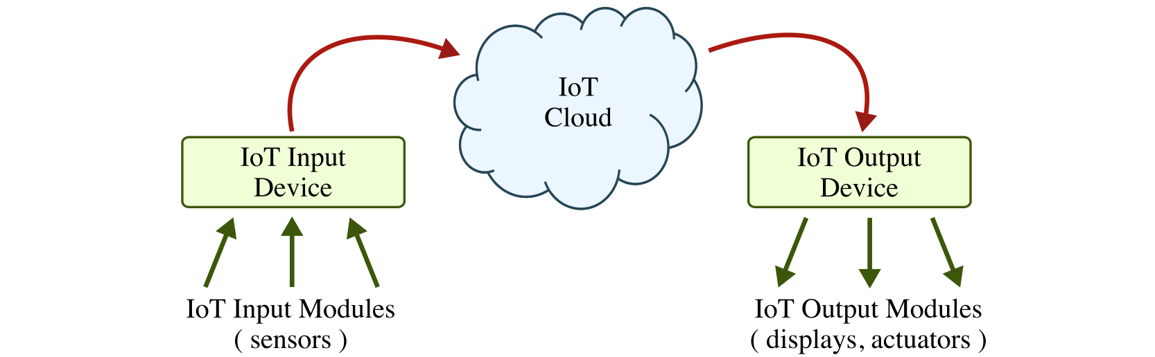
Each IoT system is comprised of an IoT input device, IoT cloud, and IoT output device. The IoT input device for this lab will include an ultrasonic rangefinder and a Particle Argon board which will monitor the sensor and communicate to the IoT cloud. The IoT output device for this lab will include an LED and a Particle Argon board which will listen for messages from the IoT cloud to indicate when it should turn on the LED. The IoT cloud will be the Particle Cloud which can be seamlessly integrated with the Particle Argon boards.
The final IoT system will work as follows: (1) the IoT input device will monitor the environment for motion, and when it senses some kind of motion it will send a message to the IoT cloud; (2) the IoT cloud will relay this message to the IoT output device; and (3) the IoT output device will trigger the LED to turn on. This IoT system is a simple example of emerging “smart homes” where various input and devices work together through the cloud to automate daily tasks and (hopefully) improve the overall quality of our lives.
We will use an incremental process to building this IoT system. First, we will divide each group of four students into two sub-groups with two students each. One sub-group will focus on building the IoT input device and the other sub-group will focus on building the IoT output device. Each sub-group will start by just building a very basic non-internet-connected device that uses an LED and the ultrasonic rangefinder. The sub-groups will then experiment with either connecting the input (i.e., ultrasonic rangefinder) or the output (i.e., LED) to the cloud. Then the sub-groups will come together to combine the IoT input device with the IoT output device to create the complete IoT system.
Part 0: Using the Particle IDE
Take a look at the materials on the lab bench which you will be using to complete the lab. Make sure you can identify all of the materials before continuing.
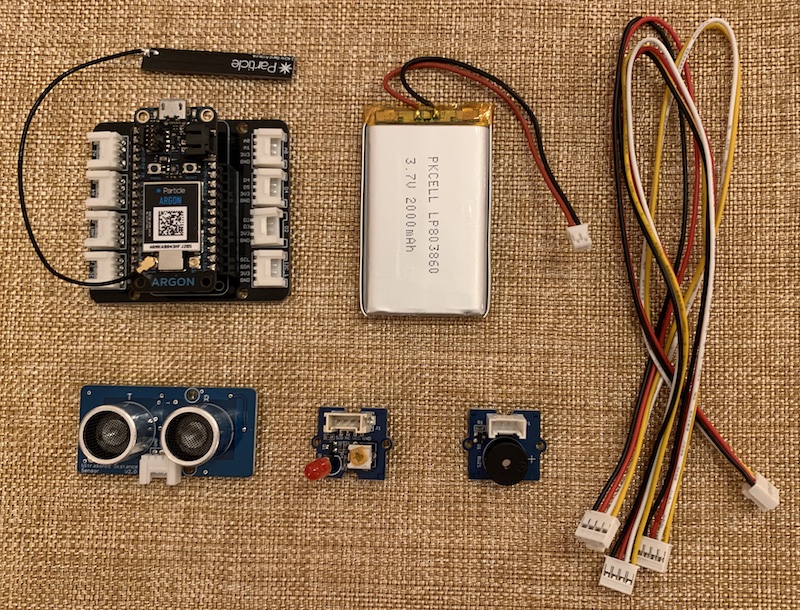
- Particle Argon board
- LiPo battery
- Ultrasonic rangefinder input module
- LED output module
- Buzzer output module
- Four-wire cables
- Enclosure (not shown in photo)
Take a closer look at the Particle Argon board. Notice that there are eight white connectors that can be used to connect the input and output modules. There is an LED on top of the Particle Argon that shows the status of the device. It should be breathing a calming cyan to indicate that the board is connected to the cloud and operating normally.
We will be using the web-based Particle IDE to program your Particle Argon. Go to this link on your laptop:
You should not create a new account. You should login with your group username and password. The following figure labels the key icons on the left-hand side of the Particle development environment:
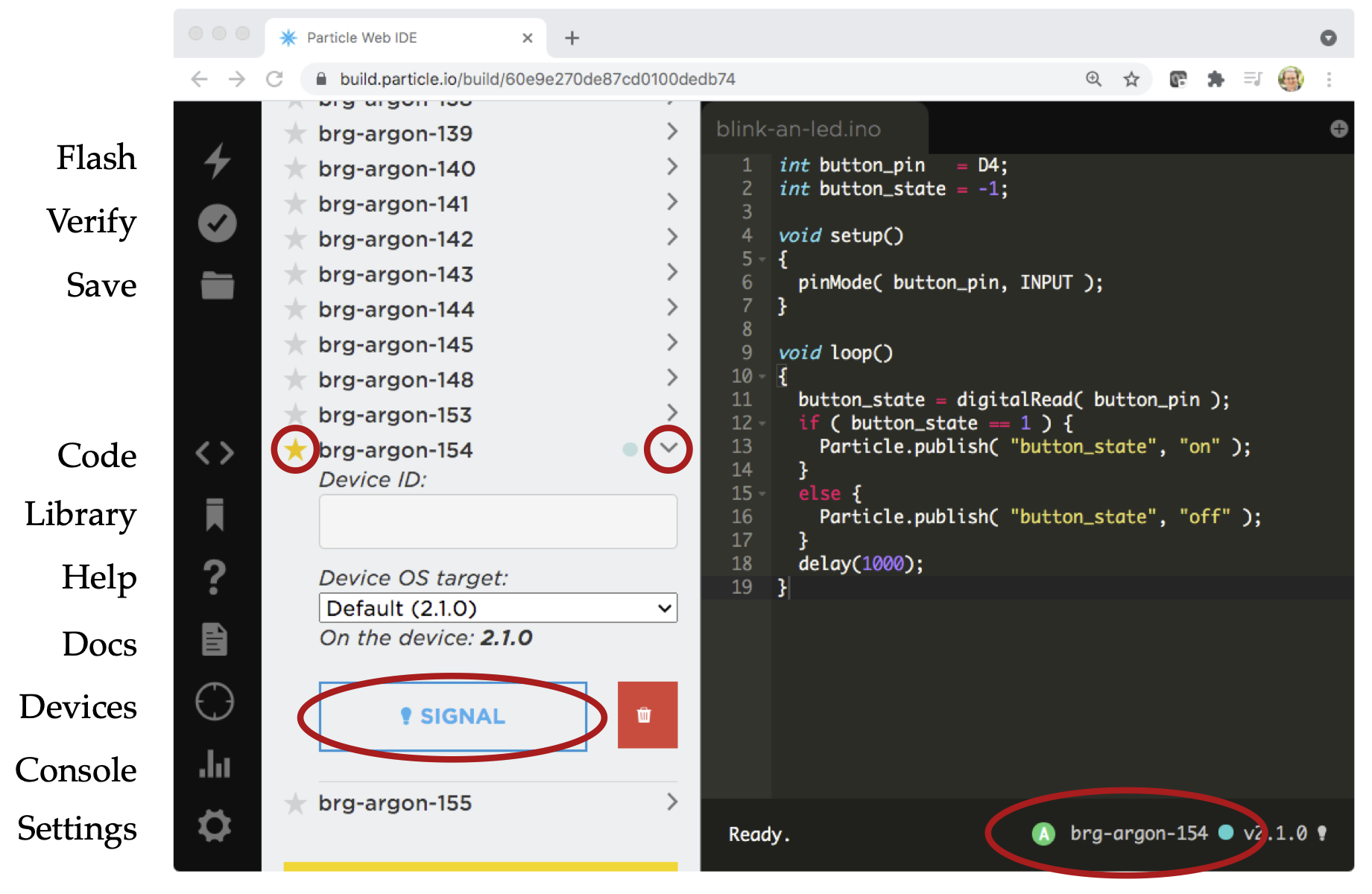
- Flash: Compiles and flashes the current code to the selected device
- Verify: Compiles without flashing the current code
- Save: Saves the current code
- Code: Shows a list of available programs
- Library: Explore libraries
- Help: Does not work for our Particle Argon
- Docs: Brings you to the Particle documentation site
- Devices: Shows a list of all devices
- Console: Brings you to the Particle console for monitoring the IoT cloud
- Settings: Log out
The most important icon is the flash (lightning) icon in the upper-left hand corner. Clicking this icon will cause the Particle IDE to compile your program into machine instructions and then to upload the resulting machine instructions to the Particle Argon for execution. The above figure illustrates what happens when you click on the devices icon. Note that you must select your specific device by clicking the little star next the device that matches your device number. You can always look at the bottom right-hand corner to verify that you are working on your specific device. You can click the little > to reveal the signal button. Clicking this button will cause your Particle Argon to blink rainbow colors which is a great way to confirm that your Particle Argon is connected to the internet and working.
Sign-Off Milestone: Signal your device and have an instructor verify that things are working correctly.
Part 1: Blinking an LED
In this part, we will start by blinking the LED output module. An LED is a “light emitting diode”. It is a simple circuit component which lights up when current flows through it. Connect the LED output module to the D4 pin using using one of the four-wire cables. Now let’s look at the software for this first part:
// Global constants for pin assignments

int led_pin = D4;

// The setup routine runs once when you press reset

void setup()
{
  // Configure led_pin to be a digital output
  pinMode( led_pin, OUTPUT );
}

// The loop routine runs over and over again

void loop()
{
  // Turn on the LED
  digitalWrite( led_pin, LOW );

  // Wait one second
  delay(1000);

  // Turn off the LED
  digitalWrite( led_pin, HIGH );

  // Wait one second
  delay(1000);
}
Before continuing, we will try and understand each line of the program. A
program consists of a sequence of statements; these statements are
executed one at a time by the microcontroller to ultimately execute the
program. An Particle program can be divided into three sections. The
first section is where we create global names for pin assignments. The
second section is the setup routine, and the third section is the
loop routine. The statements in the setup routine execute only once
at the very beginning of the program. The statements in the loop
routine execute repeatedly over and over again.
The int led_pin = D4 statement is a variable assignment. It specifies
that the variable named led_pin should be assigned the value D4. From
then on, whenever we use the name led_pin it will be interpreted as the
value D4. We also need to specify the “type” of this variable. In this
case, the type is int which indicates that this variable will store
integer values. Effectively, we are saying that the LED input module is
connected to digital input D4 on the Particle Argon. The pinMode(
led_pin, OUTPUT ) statement is a call to a routine which tells the
Particle Argon that pin number led_pin (i.e., pin number D4) should
be configured as a digital output pin.
The digitalWrite( led_pin, LOW ) statement is a call to a routine which
tells the Particle Argon to write either a logic high or a logic low
value to the pin number led_pin. The delay(1000) statement is a call
to a routine which delays execution for one second (the argument to the
routine is specified in milliseconds). These two statements turn on the
LED and wait one second. The next statements turn the LED back off and
wait another second. Since the statements in the loop execute over and
over, this program effectively turns the LED on, then off, then on, then
off, etc.
Type this program into the Particle software development environment.
Click the code icon. The input group should edit the engrg1050-input
program, and the output group should edit the engrg1050-output program.
Once you have entered your code, then click on the flash button to
download your program to Particle Argon. Be patient as this can take a
few seconds. Verify that the LED blinks appropriately. Feel free to
experiment with different delays to vary the blink rate.
Sign-Off Milestone: Once you have the LED blinking, have an instructor verify that things are working correctly.
Part 2. Using an Ultrasonic Rangefinder to Turn On LED
In this part, we will only turn on the LED when the ultrasonic rangefinder detects that something is closer than a certain threshold. Connect the ultrasonic rangefinder input module to the A4 pin using using one of the four-wire cables. Now let’s look at the software for this second part:
#include <Grove-Ultrasonic-Ranger.h>
int ranger_pin = A4;
int led_pin = D4;
Ultrasonic range_sensor( ranger_pin );
void setup()
{
pinMode( led_pin, OUTPUT );
}
void loop() {
int ranger_cm = range_sensor.MeasureInCentimeters();
if ( ranger_cm < 20 ) {
digitalWrite( led_pin, HIGH );
}
else {
digitalWrite( led_pin, LOW );
}
delay( 1000 );
}
Notice that we are configuring another pin, ranger_pin, which is then
used when constructing the Ultrasonic class. In the loop routine, we
check if the range is less than a threshold, and if so we turn on the
LED. Test out your code, and try different thresholds.
Sign-Off Milestone: Once you have the ultrasound ranger input module controlling the LED output module, have an instructor verify that things are working correctly.
Part 3a. Using an Ultrasonic Rangefinder to Send IoT Message
This part is for the IoT input sub-group. If you are in an IoT output
sub-group then you should work on Part 3b. Go ahead and disconnect the
LED output module. Leave the ultrasonic rangefinder input module
connected to the Particle Argon. In this part, you will work on sending
an IoT message to the cloud when the ultrasonic rangefinder detects
something is closer than a certain threshold. Modify the code from Part 2
to use the Particle.publish function to send an IoT message like this:
#include <Grove-Ultrasonic-Ranger.h>

int ranger_pin = A4;

Ultrasonic range_sensor( ranger_pin );

void setup()
{ }

void loop() {
  int ranger_cm = range_sensor.MeasureInCentimeters();

  if ( ranger_cm < 20 ) {
    Particle.publish( "alarm", "on" );
  }
  else {
    Particle.publish( "alarm", "off" );
  }

  delay( 1000 );
}
The Particle.publish function will send a message named “alarm” and the
message data is either “on” or “off” depending on whether we want to the
alarm on the output device to be on or off. You can verify this is
working by watching the console. Click on the console button and you
should see a “alarm/on” event show up every time you trigger the
ultrasonic rangefinder.
Sign-Off Milestone: Once you have verified that your IoT input device is able to send messages to the IoT cloud, show an instructor by using the console.
Part 3b. Using an IoT Message to Turn on LED
This part is for the IoT output sub-group. If you are in an IoT input
sub-group then you should work on Part 3a. Go ahead and disconnect the
ultrasonic rangefinder input module. Leave the LED output module
connected to the Particle Argon. In this part, you will work on receiving
an IoT message to turn on and off the LED output module. Modify the code
from Part 2 to use the Particle.subscribe function to receive an IoT
message like this:
int led_pin = D4;

void receive_msg( const char* event, const char* data )
{
  if ( strcmp( data, "on" ) == 0 ) {
    digitalWrite( led_pin, HIGH );
  }
  else {
    digitalWrite( led_pin, LOW );
  }
}

void setup()
{
  pinMode( led_pin, OUTPUT );
  Particle.subscribe( "alarm", receive_msg );
}

void loop()
{ }
The Particle.subscribe function says to call the receive_msg function
whenever the Particle Argon receives an “alarm” message. In the
receive_msg function, we check to see if the message data is either
“on” or “off” and turn on or off the LED appropriately.
Sign-Off Milestone: Before downloading your code to the Particle Argon board, have an instructor verify it is correct.
Part 5. Putting Together the IoT System
We are now ready to put together the IoT input device and the IoT output device into a complete IoT system! All we need to do is have the IoT output sub-group download their code to their Particle Argon board. Try triggering the ultrasonic rangefinder on the IoT input device, use the console to see that the message was sent into the IoT cloud, and verify that the LED on the IoT output device goes on. Once this all works, it is now time to polish up the IoT system a bit.
Consider adding an audible alarm using the buzzer. You can connect
the buzzer to the D2 pin of the IoT output device. Use pinMode to
configure the buzzer as an output in the setup function, and then write
the buzzer just like you do the LED. Use HIGH to turn the buzzer on, and
LOW to turn the buzzer off.
Put your IoT input and output devices into the small enclosures. Use some blue tape to attache the input/output modules to your device. Position the ultrasonic rangefinder on the side of the enclosure.
Now place your IoT input device in the hallway to see if you can detect students passing outside!
Sign-Off Milestone: Have an instructor verify the whole system works.